Computer vision, QR code recognition
Conveyor lines in automated factories rely on QR code tags to identify the manufactured parts and a control system is implemented to tell the robots what to do with each part. In this lecture you will learn how to detect QR codes, and how to control your robot according to the detected QR code message.
Requirements
- Ozeki 10 installed: http://www.ozeki.hu/index.php?owpn=6066
- Miner: http://www.ozeki.hu/index.php?owpn=6205
- Rocks: http://www.ozeki.hu/index.php?owpn=6275
- SNAP: http://www.ozeki.hu/index.php?owpn=6180
Create the QR codes
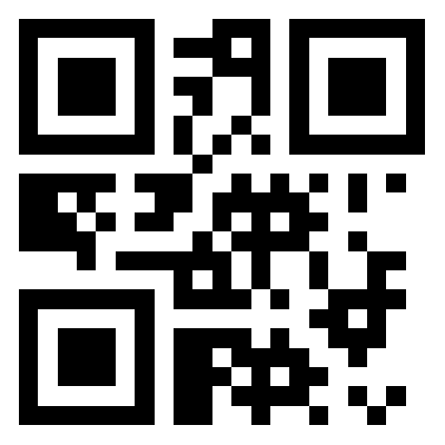
The first thing to do for your miner is to generate QR codes (Figure 1). You can use free websites to get your QR codes. You will need two codes for this lecture. The first code represents number 1 and the second code represents number 2. You are lucky, because these two numbers are also collected for you in a downloadable and printable format in the following PDF document below:

|
The PDF contains the required QR codes for this lecture By opening it you will see number 1 and 2 in three different sizes Download PDF containing the two detectable numbers |
You can generate custom QR codes at
But you are lucky that they are generated below
- QR code generated from number 1:
- QR code generated from number 2:
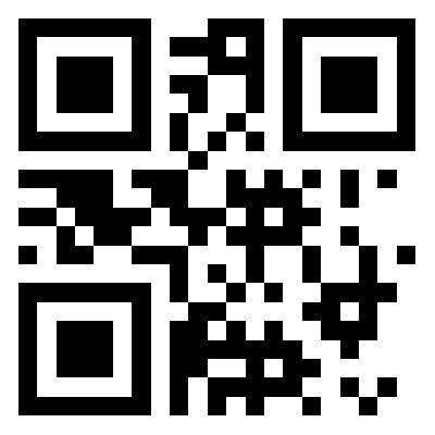
Figure 1 - These QR codes were generated at www.qrstuff.com
Connect your USB camera to your PC
First make sure the USB camera is plugged into the USB slot. After you have logged into Ozeki 10, please start the Control Panel to add the USB camera connection to the list by pressing the 'Create new Connection' button, selecting 'Video' then 'USB camera ' (Figure 2).
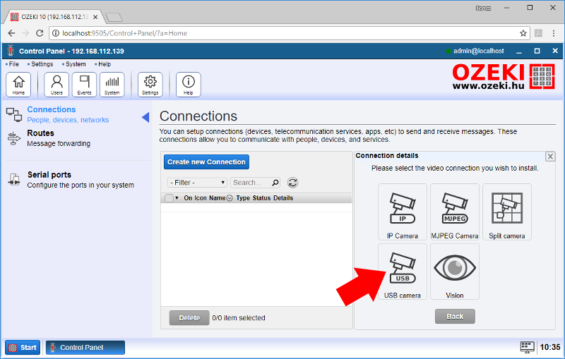
Figure 2 - Add USB camera connection
Make sure that the connected USB camera is selected. You can leave the default settings the list. 640x480 is more than enough to detect QR codes. Click 'OK' to save settings (Figure 3) and the camera will appear in Ozeki 10's connection list, which contains all connected devices.
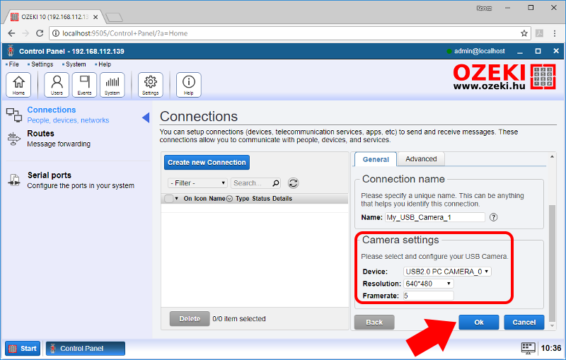
Figure 3 - Configure USB camera settings
Add QR code filter on the USB camera stream
Stay in the Control Panel and add a new connection by selecting 'Create new Connection' then select 'Video', 'Vision' and finally 'Barcode' (Figure 4). The Barcode scanner is not just what it seems, it can detect QR codes too and transform them to numbers or texts.
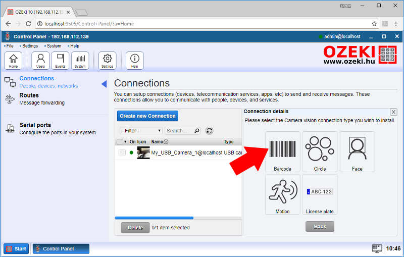
Figure 4 - Add connection that detects QR codes
In this step you simply have to put the filter on the USB camera connection. On figure 5, you can see that the filter is being added on your current camera stream. Click 'OK' and your new QR code scanner will appear in the connection list. You will find it with the following name: barcode scanner.
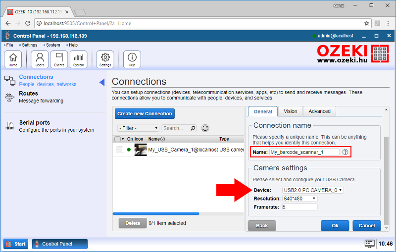
Figure 5 - Leave the USB camera in the connection settings
Test detection using chat interface
Click on the barcode scanner connection in the connection list, so you will find yourself on the configuration interface, where you can watch the live stream, change camera source, check events or chat with the barcode scanner connection. Click on 'Chat' (Figure 6) to start chatting. You can look at the command list by typing 'help'. You will have to use one command: 'subscribe' and see incoming chat messages, like 'Barcode detected. Format: QR_CODE Content: 2' seen on the figure.
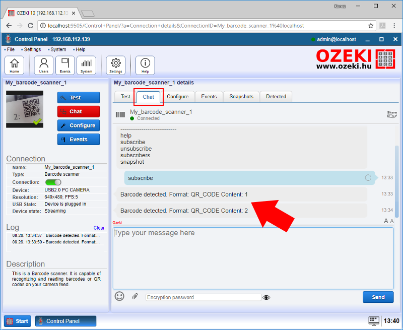
Figure 6 - Get the two QR code values through the chat interface
Write a SNAP code to display the barcode value on the Brick
The first and most important thing to do is to read the QR code and store the value any desired variable. It is very important to subscribe to the barcode sensor through SNAP, so you can read QR code values in a forever loop (Figure 7). The 6th word of each message is the string generated from the QR code. Get the 6th with the 'item [word_number] of [list]' block where the [word_number] is 6 and the [list] is another block called 'split [variable] by [character]', where the [character] is a space button and the variable is the 'msg' which stores the barcode sensor input. After reaching the 6th word, it is stored in the 'readed' variable. The stored value will be sent towards your Brick in step 2.
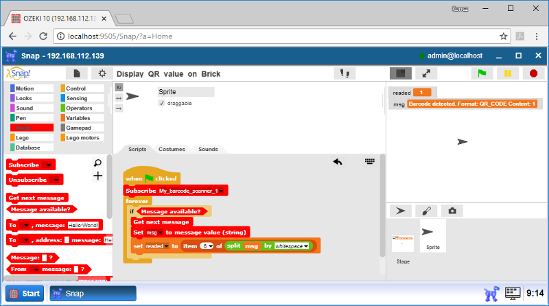
Figure 7 - This program code snippet reads the value of a QR code
Then the QR code value is displayed on the brick with 4 simple commands (Figure 8). The 1st is a 'clean' command, the 2nd command is 'fontsize large', the 3rd command is 'draw text foreground 80 60' joined with the 'readed' variable. Finally all 3 commands will modify the screen by sending an 'update', which is the 4th command. Without updating, the screen will not change.
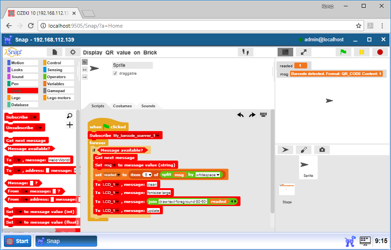
Figure 8 - This program code shows the value of any QR code on your Brick
Program code
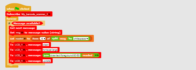
Figure 9 - Look at this code to see all required LCD commands
|
|
This program code detects QR codes and displays it on the Brick It is advised to test it with the QR codes you printed You can generate your own QR codes to display numbers or words Download the QR detection program code |
Build a Miner robot
The Miner robot can grab and move objects. It has an arm and a gripper to perform this action (Figure 10). The arm can be positioned in the 3D real world environment by using two Large motors, while the claw can grab or drop objects by using a Medium motor. The Miner can be easily built by using the guide you can reach at: http://www.ozeki.com/index.php?owpn=6205 Keep in mind the goal of this task is only building it. You will see how to move the Miner from the upcoming tasks.
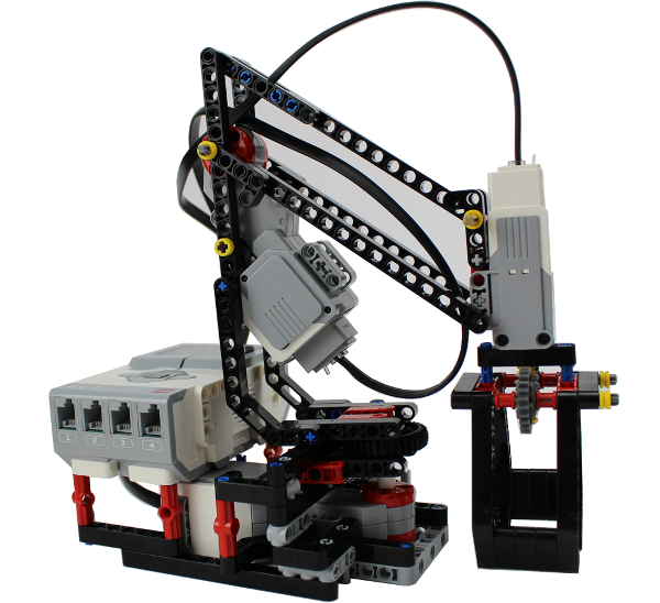
Figure 10 - This is how a Lego Miner should look like
Build 8 rocks
Rocks were designed to be easily gripped and lifted by the Miner. Here you can see how a Rock is constructed: http://www.ozeki.com/index.php?owpn=6275 Then print the QR code PDF from Task #1 and cut out number 1 and 2 QR codes with a scissor. You will need 4 number 1-s and 4 number 2-s, which you should glue on your rocks (Figure 11) to perform this lecture.
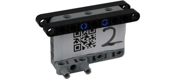
Figure 11 - The rock is the object the Miner should lift
Write the code that moves the Miner robot
It is very important to subscribe to the QR code scanner directly after the code started and read any incoming messages in a forever loop. Each message starts with a space, so you have to eliminate the space and store it in the 'msg' variable with the following block: 'set [variable] to [value]', where the variable is called 'reader' and is displayed on the top right corner. The [value] gets the number from the 'split [variable] by [character]' block, where the [variable] is the received 'msg' and it is splitted at each space [character] (Figure 12). The 6th word in the 'msg' is the QR code text.
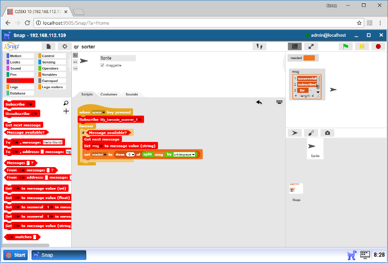
Figure 12 - The code subscribes to the scanner and saves value in 'msg'
Finally check if the value of the 'reader' is 1 or 2, which are the numbers glued on the rocks. The Miner places the rocks either left or right depending on the QR code match (Figure 13). Look at the code and see how easily the Lego motor movement blocks fit each other. The movement can differ depending on your robot. It is highly likely that you have to modify the code depending on the Miner you have built. If the arms break, you should make small modifications to the movement blocks.
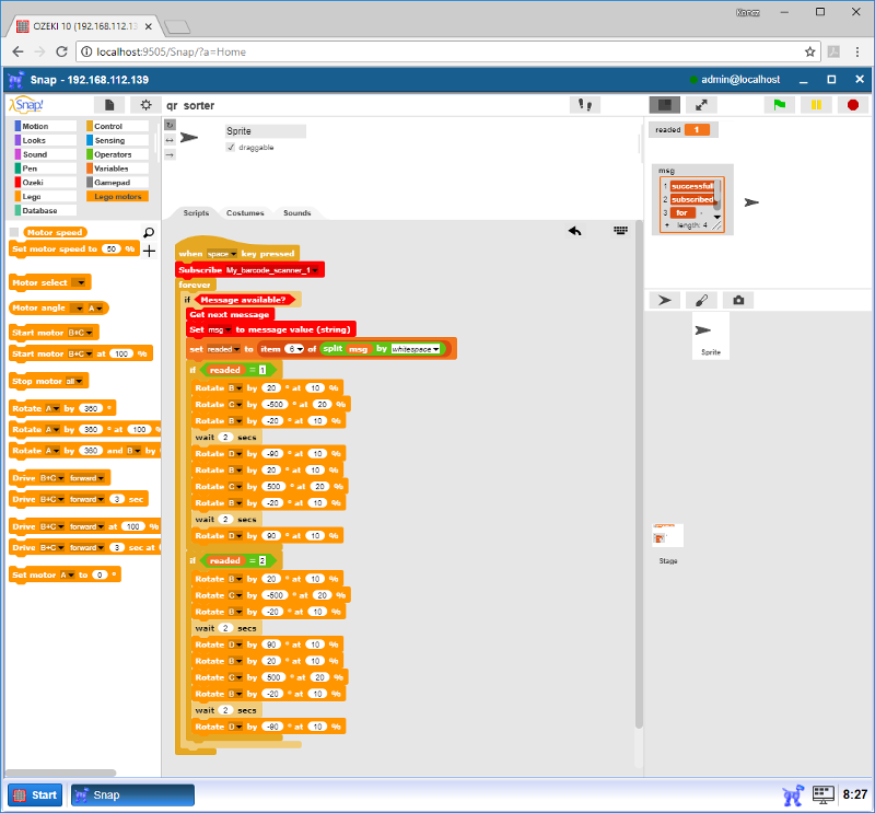
Figure 13 - This is the same SNAP code controlling the Miner in the video
Program code
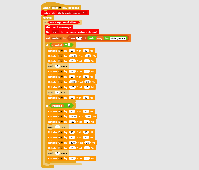
Figure 14 - With this program code the Miner can grip objects
|
|
This program code detects QR codes and moves the Miner You can watch the code work in the lecture starter video It places the rocks depending on the QR codes Download the QR detection program code |
